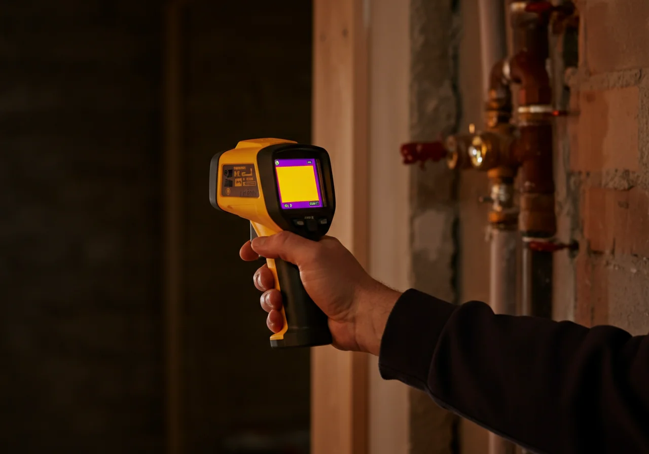
Thermal Imaging Camera
The Diagnosis: Pinpointing Subsurface Leaks with Thermal Imaging
A thermal imaging camera is a non-invasive diagnostic tool that converts infrared radiation into a visible heat map. For plumbing and HVAC professionals, its primary value in leak detection lies in its ability to visualize temperature differentials caused by escaping fluids. When tracing a hot water leak within a concrete slab, the camera detects the radiant heat signature of the leaking water as it spreads through the substrate, often revealing the leak’s location and path long before surface damage appears.
Technical Deep Dive: Procedure for Slab Leak Detection
Success requires a methodical approach to isolate the thermal signature of the leak from ambient conditions. Follow this step-by-step protocol.
- Step 1: Pre-Condition the System. Isolate the suspected leak zone by closing other zone valves. Run the hot water supply continuously for a minimum of 30-45 minutes to ensure the leaking water is significantly warmer than the surrounding slab. The greater the temperature delta, the clearer the image.
- Step 2: Control the Environment. Conduct the scan during stable thermal conditions. Avoid direct sunlight on the scan area, and shut off in-floor radiant heat in adjacent zones. Close doors and windows to minimize air drafts that can distort surface temperatures.
- Step 3: Systematic Scanning. Using a camera like a FLIR C5 or Bosch GTC 400 C, start from the area of suspicion (e.g., a warm floor spot) and scan in a grid pattern. Hold the camera perpendicular to the floor, approximately 6-8 feet away for an initial wide view, then move closer for detail. The leak will typically appear as an anomalous warm “blob” or streak that follows a logical path (along a pipe run or towards a drain).
- Step 4: Image Analysis & Verification. Use the camera’s software to adjust the palette (ironbow is often best for high contrast) and set appropriate span/level. Mark the thermal anomaly with chalk. Corroborate findings with a moisture meter. A true leak will show both elevated temperature and moisture content.
- Step 5: Post-Repair Verification. After repair, perform a follow-up scan under identical conditions to confirm the anomalous heat signature has been eliminated, ensuring no secondary leaks exist.
Code & Compliance: Supporting Evidence and Best Practices
While thermal imaging itself is not directly mandated by code, its use supports compliance with critical plumbing and building standards by enabling precise, minimally invasive diagnostics.
- IPC 2021, Chapter 3 (General Regulations): Section 307.1 requires concealing piping in a manner that allows for access and repair. Thermal imaging identifies the exact breach point, allowing for a targeted repair that minimizes slab destruction, aligning with the code’s intent for repairable systems.
- OSHA 1926.20(b)(1) – General Safety: The use of non-contact diagnostics like thermal imaging falls under the “general duty” to employ methods that reduce hazard exposure. It limits the need for immediate, exploratory jackhammering, reducing silica dust exposure and trip hazards.
- IBC (International Building Code) – Durability: Undetected moisture from slab leaks can compromise structural rebar and subfloor materials. Early detection via thermal imaging helps maintain the structure’s long-term integrity as intended by the code.
Toolbox: Essential Gear for Reliable Diagnostics
Accuracy is non-negotiable. Your diagnostic kit should include:
| Tool | Purpose | Example Brands/Models |
|---|---|---|
| Thermal Imaging Camera | Primary device for visualizing temperature differentials. Look for a thermal sensitivity (NETD) of <80mK and MSX® (Multispectral Dynamic Imaging) technology for clearer edges. | FLIR E8, Bosch GTC 600 C |
| Pin & Pinless Moisture Meter | Correlative tool to verify elevated moisture levels at the thermal anomaly. | General Tools, Milwaukee |
| Digital Multimeter | To verify electrical disconnects for safety before any coring or cutting near the identified site. | Fluke 117, Klein Tools MM700 |
Understanding Radiant Heat Signatures
Radiant heat is the energy emitted from a warm object, in this case, water escaping a pipe and transferring heat to the surrounding concrete. The camera detects this emitted infrared radiation, not the water itself. Key factors affecting the signature include:
- Thermal Mass & Conductivity: Concrete has high thermal mass, meaning it heats and cools slowly. A leak creates a slow-moving, spreading thermal plume.
- Latent Heat of Vaporization: As water evaporates at the edge of the leak plume, it cools. This can sometimes create a cooler ring around the warm spot, a secondary indicator.
- Pipe Depth & Insulation: Deeper pipes or insulated slabs will show a more diffuse, less distinct thermal anomaly, requiring longer system pre-conditioning.
Safety Warning & Limitations
SAFETY WARNING: Before any verification that involves cutting or coring, you MUST shut off the water supply to the affected line and lock out/tag out any electrical circuits in the work area. Thermal imaging indicates a probable leak location; it is a diagnostic aid, not a standalone verification tool. Always confirm with a moisture meter and visual inspection post-excavation.
Technical Limitations: Thermal cameras cannot see through walls or slabs; they only read surface temperatures. They are less effective on very well-insulated floors, with cold water leaks (unless using a cooling injection method), or in environments with extreme thermal interference.
External Reference for Further Study
For an in-depth technical explanation of infrared thermography principles and standards, refer to the resource from the National Institute of Standards and Technology (NIST): NIST: How Do You Measure Thermal Imaging Cameras?. This provides foundational knowledge on calibration and measurement science critical for accurate interpretation.