Calibration Gauge Use
The Diagnosis: Verifying Crimp Tool Performance with a Calibration Gauge
A calibration gauge, specifically a Go/No-Go gauge, is the definitive quality control tool for verifying that your manual crimping tool is producing connections within the manufacturer’s specified mechanical and electrical tolerances. An out-of-tolerance crimp can lead to high resistance, heat buildup, premature corrosion, and catastrophic system failure. This guide details the precise procedure for using a Go/No-Go gauge to audit your crimping tool’s performance, ensuring every connection meets code and engineering standards.
Technical Deep Dive: The Calibration Verification Procedure
This process is not a substitute for factory calibration but a critical field verification check. Perform this test at the start of each work session or after any event that could affect tool alignment (e.g., a drop, heavy use, or die change).
Step 1: Preparation and Sample Creation
- Tool Isolation: Use the specific manual crimping tool and die set you are verifying. Ensure it is clean and free of debris.
- Material Specification: Use a new, correct-sized terminal and a piece of wire that matches the tool’s die marking exactly (e.g., 10 AWG). Do not use scrap wire.
- Sample Crimp: Create a crimp sample following the tool manufacturer’s instructions: insert the terminal, position the wire, and execute a full, firm crimp until the tool’s mechanism fully cycles or releases.
- Visual Inspection First: Examine the sample. The wire insulation should not be within the crimp barrel, and the terminal should not be visibly deformed or cracked.
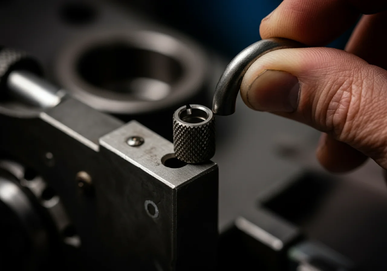
Step 2: Applying the Go/No-Go Gauge
The Go-No-Go gauge is a precision block of metal with two critical features: a “Go” slot and a “No-Go” slot, machined to the minimum and maximum acceptable crimp dimensions.
- The “Go” Side Test: The crimped terminal barrel (the insulated section if it’s an insulated terminal) must fully enter the “Go” slot of the gauge under its own weight or with very light pressure. If it does not fit, the crimp is under-sized (too tight), which can crush conductors and increase resistance.
- The “No-Go” Side Test: The crimped terminal barrel must NOT fit into the “No-Go” slot. If it enters, even partially, the crimp is over-sized (too loose), resulting in poor mechanical grip and insufficient electrical contact.
Step 3: Interpretation and Action
| Test Result | Diagnosis | Corrective Action |
|---|---|---|
| Passes “Go”, Fails “No-Go” | Crimp is within tolerance. Tool is verified for use. | None. Proceed with work. |
| Fails “Go” (Does not fit) | Undersized Crimp. Tool may be misadjusted, worn, or wrong die set. | 1. Check for die mismatch. 2. Inspect tool for damage. 3. Tool likely requires professional recalibration by the manufacturer or authorized center (e.g., Milwaukee Service). |
| Passes “No-Go” (Fits into slot) | Oversized Crimp. Tool is worn, loose, or not fully cycling. | 1. Ensure tool is fully cycled on each crimp. 2. Check for wear on dies and ratchet mechanism. 3. Tool requires professional service or replacement. |
Code & Compliance: The Standard Behind the Gauge
The use of calibrated tools and verification methods is implicitly or explicitly required by multiple governing standards to ensure system integrity and safety.
- National Electrical Code (NEC) 110.3(B): Mandates that listed equipment (including terminals and connectors) must be installed and used in accordance with manufacturer’s instructions. Manufacturer instructions universally require proper crimping with a verified tool.
- NEC 110.14: Requires electrical connections to be mechanically and electrically secure without damaging the conductors. A verified crimp is the primary method of compliance for solderless connections.
- OSHA 1910.334 & 1926.416: These standards require the use of proper tools and equipment for the work being performed. Using an unverified, out-of-tolerance crimping tool violates this principle.
- Quality Assurance Protocols: NFPA 70B (Recommended Practice for Electrical Equipment Maintenance) and manufacturer warranties often require documented tool calibration and verification records.
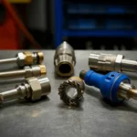
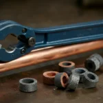
Toolbox: Essential Equipment for Verification
- Calibration (Go/No-Go) Gauge: Must be specific to the terminal manufacturer and series (e.g., Panduit PAN-GNGO, TE Connectivity). Using the wrong gauge invalidates the test.
- Dedicated Crimping Tool: A quality, ratcheting manual tool like those from Ridgid or Klein Tools. Non-ratcheting tools are not suitable for consistent, verifiable work.
- Wire Stripper: A precision stripper to remove insulation without nicking the conductor strands, which can lead to failure under the crimp.
- Measurement Backup: While not a replacement for the gauge, a high-quality digital micrometer (e.g., Fluke digital calipers) can be used for additional dimensional checks if gauge results are ambiguous.
Safety Warning & Best Practices
WARNING: Always de-energize and lock out/tag out (LOTO) any circuit before performing crimping operations. A failed crimp can overheat and cause fire or equipment damage. Never use a crimping tool that fails the Go/No-Go verification. The verification sample is for test purposes only—do not install it in a live system.
Best Practices: Maintain a calibration log for each tool. Store gauges in a protective case to prevent nicks or dings that affect their precision. Purchase terminals and matching gauges from the same manufacturer to ensure compatibility.
External Reference for Technical Definitions
For a foundational understanding of measurement and calibration principles that underpin Go/No-Go gauge design, refer to the National Institute of Standards and Technology (NIST) overview on measurement accuracy and traceability. This resource explains the critical concept of traceable standards, which is what your calibration gauge ultimately represents.