Bradford White Status Light
Diagnosing Your Bradford White Water Heater: The Status Light Decoded
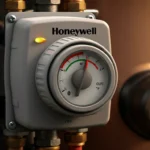
The Bradford White status light is a critical diagnostic tool integrated into the Honeywell gas control valve (GCV). This flashing LED provides a coded visual indication of the unit’s operational state or a specific fault condition. For technicians and advanced homeowners, correctly interpreting these flashes is the first and most crucial step in troubleshooting a non-functioning gas water heater, particularly when facing issues like a gas valve failure or problems with the pilot assembly.
Technical Deep Dive: Interpreting Honeywell Valve Flash Codes
The status light behavior follows a specific pattern. A steady light indicates normal operation. Flashing signals require interpretation. The flash sequence is a series of rapid flashes, a pause, and then a repetition. Count the number of flashes in each sequence before the pause.
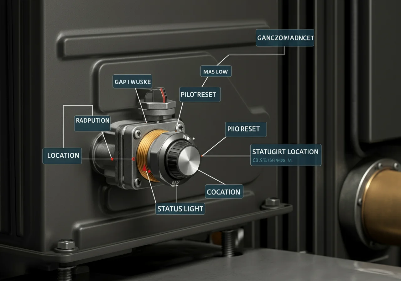
- Locate the Light: Find the Honeywell gas control valve. The status LED is a small, red (or sometimes green/red) light typically visible through a sight glass on the valve body or on the thermostat knob.
- Observe the Pattern: Watch the light for a full minute to establish the repeating flash code pattern. Use a notepad or your phone to record the sequence.
- Count the Flashes: The number of flashes correlates to a specific diagnostic code. Common Honeywell codes for Bradford White heaters include:
| Flash Code | Probable Condition | Primary Components to Check |
|---|---|---|
| 1 Flash | Normal operation (after ignition), or “Lockout” – valve shut down after multiple failed ignition attempts. | If no hot water, follow lockout reset procedure. Check gas supply, thermopile, and pilot. |
| 3 Flashes | Pressure Switch Fault. The switch did not close or opened during operation. | Vent blockage, draft inducer motor (if equipped), pressure switch tubing, or a failed switch. |
| 4 Flashes | Gas Valve / Solenoid Fault. The valve detected an issue with its internal circuitry or coil. | This often points directly to a gas valve failure. Check valve coil resistance with a multimeter. |
| 5 Flashes | Ignition / Flame Sense Fault. Pilot did not light, or flame signal was lost. | Pilot assembly (clogged orifice, weak flame), thermopile/coupler (low mV output), or grounding issue. |
| 7 Flashes | Limit Switch Open. Water temperature exceeded safe limit. | High thermostat setting, failed upper thermostat, or a physical limit switch that needs manual reset. |
Step-by-Step Troubleshooting for Critical Codes
For 4 Flashes (Suspected Gas Valve Failure):
- Confirm Power: Verify 24-28V AC is present at the valve terminals from the thermostat circuit. Use a reliable multimeter like a Fluke 116.
- Check Coil Resistance: With power OFF and wires disconnected, measure resistance across the gas valve’s solenoid coil terminals. Consult the specific Honeywell valve manual; typical resistance should be in the range of 40-200 ohms. An open circuit (infinite resistance) or a short (near zero) confirms valve coil failure.
- Inspect Wiring: Look for damaged, corroded, or loose connections at the valve and thermostat.
- Conclusion: If voltage is correct but the valve does not open audibly, and coil resistance is out of spec, the gas control valve requires replacement. This is not a user-serviceable part. The entire gas control valve must be replaced as a certified assembly by a licensed technician.
For 5 Flashes (Pilot/Flame Sense Issue):
- Visual Pilot Inspection: Attempt to light the pilot per the unit’s instructions. Observe the flame. It should be steady, blue, and strong enough to engulf 3/8″ to 1/2″ of the thermopile/thermocouple tip. A weak, yellow, or lifting flame indicates a clogged pilot orifice or incorrect gas pressure.
- Clean the Pilot Assembly: Shut off gas and air. Use compressed air or a fine wire (like a guitar string) to gently clear the pilot orifice. Reassemble carefully.
- Test the Thermopile/Thermocouple: With the pilot lit, use a multimeter set to DC millivolts (mV). Place one lead on the thermopile’s connector at the gas valve and the other on the valve body (ground). A healthy thermopile should generate 650-850 mV under load. A thermocouple should produce 18-30 mV. If output is below 150 mV for a thermopile, it cannot hold the gas valve solenoid open and must be replaced.
- Check for Grounding Issues: A poor ground at the thermopile bracket or gas valve can cause intermittent flame sense loss. Ensure all connections are clean and tight.
Code & Compliance: The Regulatory Backdrop
All work on gas-fired water heaters is governed by strict codes to ensure safety. The International Fuel Gas Code (IFGC) and Uniform Plumbing Code (UPC) Sections 5 and 6 dictate proper installation, venting, and gas line sizing. More critically, NFPA 54 (National Fuel Gas Code) is the paramount standard. Replacement of a gas control valve is considered gas appliance repair, which under most jurisdictional interpretations of these codes requires a licensed gas fitter or plumber. Tampering with a certified gas valve assembly may also void the appliance’s listing (typically from ANSI Z21.10.1) and your homeowner’s insurance coverage in the event of an incident.
The Professional Toolbox
Accurate diagnosis requires the right instruments. For electrical testing, a true-RMS digital multimeter like the Fluke 87V or Fieldpiece HS36 is indispensable. For gas pressure measurement, a quality manometer such as a UEi DP-1000 or Testo 510i is required to verify inlet and manifold pressure per manufacturer specs. Basic hand tools from brands like Milwaukee (for cordless efficiency) and Ridgid (for pipe wrenches and thread-sealing compounds) form the core of any service truck.
External Reference & Further Reading
For the definitive technical specifications, wiring diagrams, and code interpretations for your specific Honeywell gas control valve model, always refer to the official manufacturer’s documentation. You can find a comprehensive library of technical bulletins and manuals at the Honeywell Technical Literature Portal. This resource is essential for verifying flash code meanings and component tolerances for your exact valve revision.
Final Technical Note: The Bradford White status light system is designed for diagnosis, not indefinite operation with a fault. A unit in lockout (single flash with no operation) is protecting itself and your property. Repeated resetting without correcting the underlying issue—be it a failing gas valve, a compromised pilot assembly, or a venting problem—is unsafe and can lead to hazardous conditions including gas accumulation or carbon monoxide production. When in doubt, professional intervention is not a cost; it’s an investment in safety and code-compliant operation.