Diagnosing a Faulty Water Heater Thermostat with a Multimeter
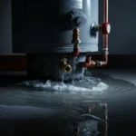
A non-functional electric water heater thermostat—either stuck closed (causing no heat) or stuck open (causing constant heating and potential safety shutoff)—is a primary culprit behind lack of hot water. Accurate diagnosis requires a digital multimeter to perform voltage and continuity tests on the thermostat, heating elements, and high-limit switch. This guide provides the step-by-step procedure for professional-grade troubleshooting.
Technical Deep Dive: Systematic Thermostat & Element Testing
Follow this sequence to isolate the faulty component. You will need a reliable digital multimeter (e.g., Fluke or Klein Tools) capable of measuring AC voltage (up to 250V) and resistance (Ohms).
Step 1: Initial Voltage Presence Test (Power On)
This test checks if voltage is reaching the thermostat. For this step only, you will turn the power back ON. Exercise extreme caution.
- Re-energize the circuit breaker.
- Set the multimeter to AC Volts (~V) on a scale higher than 240V.
- Remove the upper access panel and insulation. Identify the upper thermostat.
- With the probes, carefully measure between the two screw terminals where the LINE wires (typically black and red) connect. You should read approximately 240V.
- Next, measure between the two screw terminals feeding the upper heating element. If the thermostat is calling for heat and is functional, you should also read ~240V here. A reading of 0V indicates a problem with the thermostat or the high-limit switch.
- Turn the breaker OFF again before proceeding to continuity tests.
Step 2: Continuity Testing of Heating Elements
A failed element is a common failure point. Test both the upper and lower elements for element continuity and a ground fault.
- Disconnect the wires from one element’s terminals.
- Set the multimeter to resistance (Ohms, Ω).
- Touch one probe to each of the element’s terminals. A good element typically shows a resistance between 10-16 ohms. A reading of OL (Open Loop) or infinity indicates a blown element.
- Ground Fault Check: Set the multimeter to continuity (beep mode) or a high Ohms scale. Touch one probe to an element terminal and the other to the bare metal tank or the element’s mounting flange. The meter should read OL (no continuity). Any continuity indicates the element has shorted to ground and must be replaced.
- Repeat for the second element.
Step 3: Testing the Thermostat and High-Limit Switch
Most electric water heaters use a single-toggle, double-pole thermostat combined with a resetting high limit (energy cut-off) switch. Test them separately.
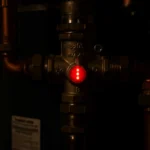
A. Testing the High-Limit Switch
- Locate the high-limit switch, usually the red button located on the upper thermostat assembly.
- With wires disconnected and power OFF, set the multimeter to continuity.
- Place probes on the two switch terminals. You should have continuity. Press the reset button; continuity should remain. If there is no continuity, the high-limit switch has failed and the entire thermostat assembly must be replaced.
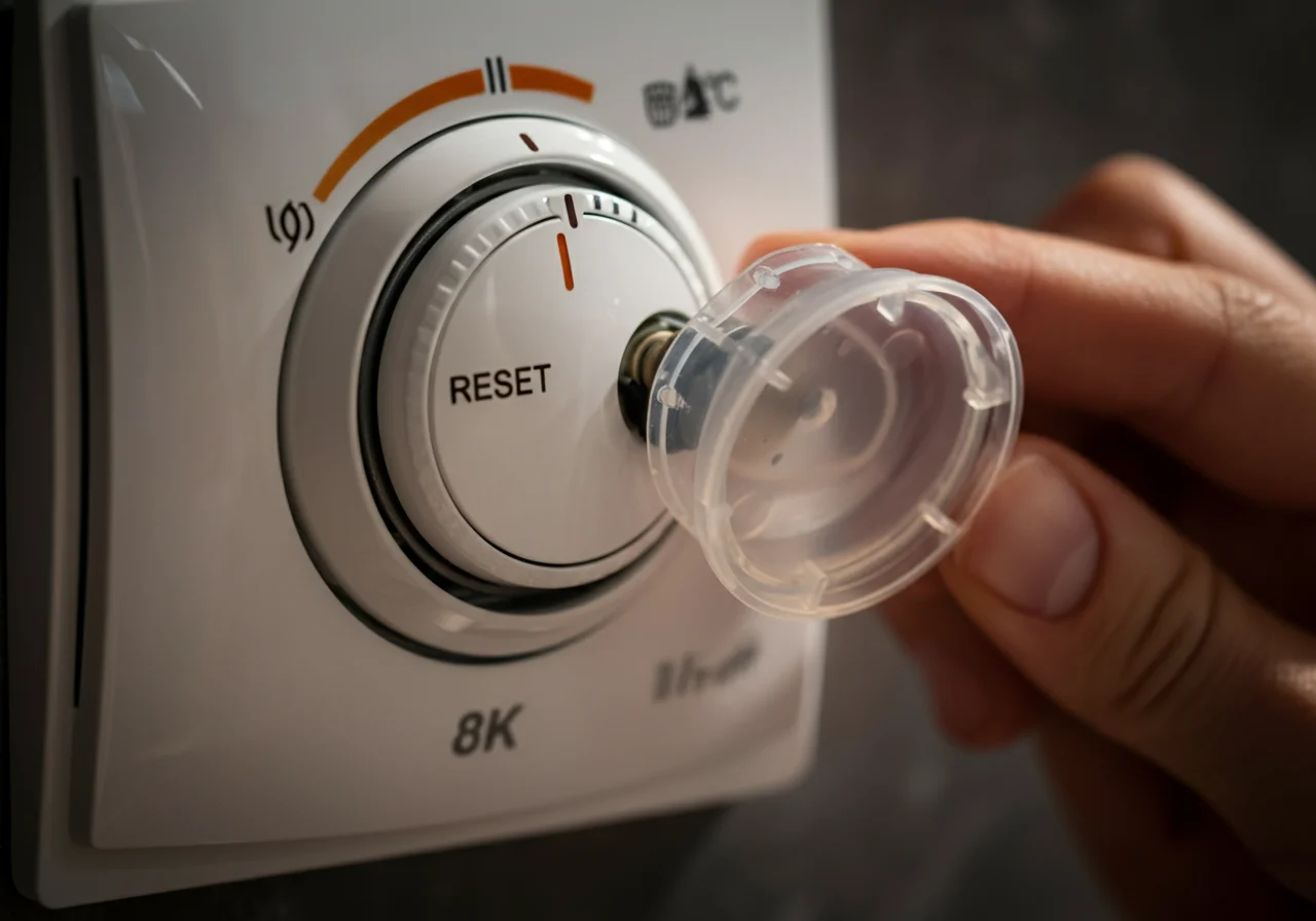
B. Testing the Thermostat Mechanism
- Identify the thermostat’s LINE and LOAD terminals.
- Set the multimeter to continuity.
- With the temperature dial set below the current tank temperature (simulating a call for heat), test across the LINE and LOAD terminals for each pole. You should have continuity on both.
- Turn the temperature dial to its lowest setting (or use a magnet on the switch for bi-metal types) to simulate a satisfied thermostat. Continuity should now be broken (OL reading).
- A thermostat that shows continuity in both states is stuck CLOSED. A thermostat that shows no continuity when calling for heat is stuck OPEN.
| Component | Test Type | Normal Reading | Faulty Reading | Indicates |
|---|---|---|---|---|
| Heating Element | Resistance (Ω) | 10 – 16 Ω | OL (Infinity) | Blown Element |
| Heating Element | Continuity to Ground | No Continuity (OL) | Continuity (Beep) | Element Shorted to Tank |
| Thermostat (Calling for Heat) | Continuity | Continuity (Beep) | No Continuity (OL) | Stuck OPEN |
| High-Limit Switch | Continuity | Continuity (Beep) | No Continuity (OL) | Failed Safety Switch |
Code & Compliance: Installation & Safety Mandates
All repairs must adhere to national and local codes to ensure safety and system integrity.
- National Electrical Code (NEC) Article 422: Governs the installation and branch-circuit requirements of fixed electric water heaters. Requires a dedicated circuit and proper overcurrent protection.
- IPC (International Plumbing Code) Section 507: Mandates the installation of a temperature and pressure relief (T&P) valve. A stuck-closed thermostat causing overheating makes a functional T&P valve critical to prevent tank explosion.
- OSHA (29 CFR 1910.333): Standards for selection and use of work practices, including locking out and tagging out (LOTO) energy sources during servicing.
- Replacement thermostats and elements must match the voltage (240V) and wattage rating specified on the water heater’s nameplate. Mismatching can cause fires or persistent tripping.
Toolbox: Essential Gear for the Job
- Digital Multimeter: A true-RMS meter like a Fluke 116 or Milwaukee MULTIMETER is recommended for accuracy and durability.
- Non-Contact Voltage Tester: For initial and verification safety checks (e.g., Fluke 1AC-A1-II).
- Insulated Screwdrivers & Nut Drivers: For panel and terminal access.
- Element Wrench: A deep-well socket or specialized wrench (e.g., Ridgid model) for removing the heating element without damage.
External Reference for Technical Specifications
For detailed, model-specific wiring diagrams and component specifications, always consult the manufacturer’s installation and service manual. As a generic reference for residential electric water heater operation and safety standards, the U.S. Department of Energy provides a comprehensive overview:
DOE Energy Saver: Water Heating.
Conclusion: A Methodical Approach
Diagnosing a water heater thermostat issue is a process of elimination using a multimeter. Always start with safety—verify power is off. Test voltage at the thermostat to confirm power supply, then proceed to continuity tests for the elements, high-limit switch, and finally the thermostat contacts. By following this structured protocol and adhering to electrical codes, you can reliably identify whether the fault lies with a stuck switch, a blown element, or a tripped safety device, enabling a precise and safe repair.