Vent Damper Failure
Vent damper failure is a critical fault in gas-fired appliances that prevents the safe operation of the burner. When the automatic damper in the flue vent fails to open, it blocks the path for combustion gases to exit, causing the appliance’s safety controls to lock out and halt ignition. This guide provides a systematic, code-compliant approach to diagnosing and resolving this common issue, focusing on water heaters and furnaces.
The Diagnosis: Understanding the System
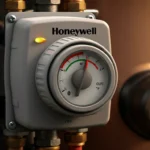
A power-venting or induced-draft appliance uses an automatic vent damper—either a motorized flapper or a guillotine-style blade—to seal the flue when the appliance is off, preventing conditioned air loss. Upon a call for heat, the damper must open fully before the ignition sequence begins. A vent damper failure is diagnosed when the appliance attempts to start but shuts down, often with a series of ignition attempts (short cycling), and no flame is established. The primary safety device monitoring this is the draft safeguard switch or spill switch, which will interrupt power to the gas valve if proper venting is not proven.
Technical Deep Dive: Step-by-Step Troubleshooting
SAFETY WARNING: Before any inspection, turn off the electrical power to the appliance at the breaker and shut off the manual gas shutoff valve. Allow the unit to cool completely. Verify the absence of voltage with a multimeter.
Step 1: Visual and Manual Inspection
- Access the Damper Assembly: Locate the damper, typically at the vent outlet on the appliance or in the first foot of horizontal vent pipe.
- Check for Obstructions: Visually inspect for bird nests, debris, or severe rust that could physically jam the damper blade.
- Manual Operation: With power and gas OFF, carefully try to move the damper blade by hand. It should move freely without binding. Note any grinding or resistance.
Step 2: Electrical Circuit Verification
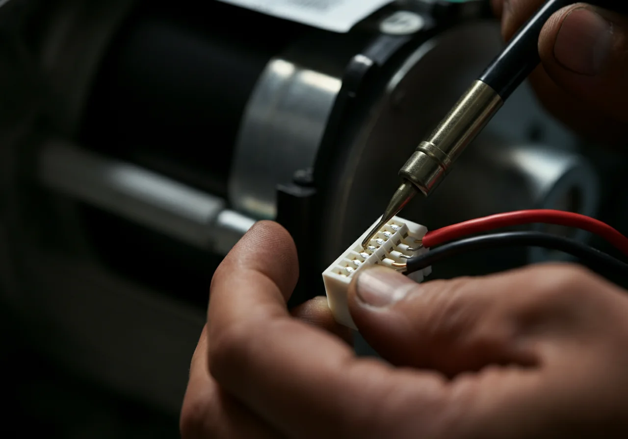
- Test Damper Motor/Actuator: Using a multimeter set to Volts AC, restore power and initiate a call for heat. Check for 120V or 24V (depending on the system) at the damper motor terminals. No voltage indicates a problem upstream in the control circuit.
- Check End Switches: Most dampers have an “end switch” or “proving switch” that closes only when the damper is fully open, allowing the sequence to continue. Use a multimeter set to Ohms (Ω) to test for continuity across this switch when the damper is commanded open. No continuity confirms a faulty switch or linkage.
Step 3: Draft and Spill Switch Analysis
The draft hood (on natural draft appliances) or draft diverter is a critical component that ensures proper draft induction. A blocked or misaligned hood can cause spillage. The spill switch (a temperature-sensitive or pressure-sensing device) is typically mounted near the draft hood or in the burner compartment.
- Test the Spill Switch: Disconnect its wires and use the multimeter in Ohms mode to check for continuity. A normally closed switch should show continuity when cool. Manually heat the switch sensor with a heat gun (carefully); it should open (show no continuity). A switch that is open when cool is faulty and will prevent operation.
- Perform a Draft Test: With the appliance reassembled and powered, use a draft gauge or a smoke pencil at the draft hood opening during burner operation. You should see a steady draw of smoke into the hood. Spillage (smoke exiting the hood) indicates a vent blockage, undersized flue, or negative pressure issues in the house.
Step 4: Control Board and Sequence of Operation
Modern appliances follow a strict ignition sequence. Consult the unit’s wiring diagram.
- Call for heat initiates.
- Vent damper actuator is energized and opens.
- Damper end switch closes, signaling the control board.
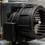
- Inducer fan (if present) energizes.
- Pressure switch (proving inducer draft) closes.
- Ignition and gas valve sequence begins.
A failure at any point will stop the sequence. Use your multimeter to trace voltage through this sequence to isolate the faulty component.
Code & Compliance
All repairs must adhere to mechanical and fuel gas codes to ensure safety and legality.
- International Fuel Gas Code (IFGC) & Uniform Plumbing Code (UPC): Section 504 covers appliance venting. Code mandates that automatic vent dampers must be listed for the appliance and must be part of a safety system that prevents burner operation if the damper fails to open (IFGC 504.8).
- National Fuel Gas Code (NFPA 54): Section 9.6 details requirements for draft hoods and venting, emphasizing that the draft hood must not be altered or obstructed.
- OSHA & Best Practices: Always follow lockout/tagout procedures when working on electrical components. Combustion analysis after a repair is a best practice to verify safe operation and efficiency.
Toolbox
Using professional-grade tools ensures accurate diagnostics.
| Tool | Purpose | Example Brand/Type |
|---|---|---|
| Digital Multimeter | Measuring voltage, continuity, and resistance in circuits and switches. | Fluke 116 HVAC Multimeter |
| Combustion Analyzer | Final verification of draft, oxygen, and carbon monoxide levels post-repair. | Testo 310 or similar |
| Draft Gauge / Smoke Pencil | Qualitative and quantitative measurement of flue draft. | Fieldpiece DG8 Draft Gauge |
| Hand Tools | Disassembly of venting and access panels. | Milwaukee M12 Cordless Screwdriver, Ridgid wrenches |
Common Failure Modes & Solutions
| Symptom | Likely Cause | Corrective Action |
|---|---|---|
| Damper motor hums but does not open | Binding blade, failed gear train in actuator, or low voltage. | Clean and lubricate pivot points (if allowed by manufacturer). Replace the damper actuator assembly. |
| Damper opens but burner still won’t fire | Faulty damper end switch or wiring to the control board. | Test and replace the end switch or repair broken wires. |
| Intermittent lockout, especially in windy conditions | Marginal draft causing the spill switch to trip. | Perform a thorough draft test. Check for vent termination issues, blocked chimney cap, or house depressurization. |
| Burner fires but spill switch trips shortly after | Restricted flue, deteriorated chimney liner, or insufficient draft hood clearance. | Inspect and clean the entire vent system. Ensure the draft hood is not immersed in flue gases and is installed per manufacturer specs. |
External Reference
For a foundational understanding of the principles of venting and draft, the Wikipedia entry on Flue Gas Stacks provides useful technical context on natural and induced draft. Always defer to the specific appliance manufacturer’s installation and service manual for definitive technical data.
Final Verification
After replacing any component—be it the damper actuator, spill switch, or cleaning the vent—a full operational test is mandatory. Restore power and gas, initiate a call for heat, and visually confirm the damper opens fully before ignition. Use a combustion analyzer to verify a stable, negative draft pressure in the flue and check for the presence of carbon monoxide in the combustion gases. A persistent vent damper failure often points to a systemic issue; when in doubt, consult a licensed HVAC or plumbing professional.