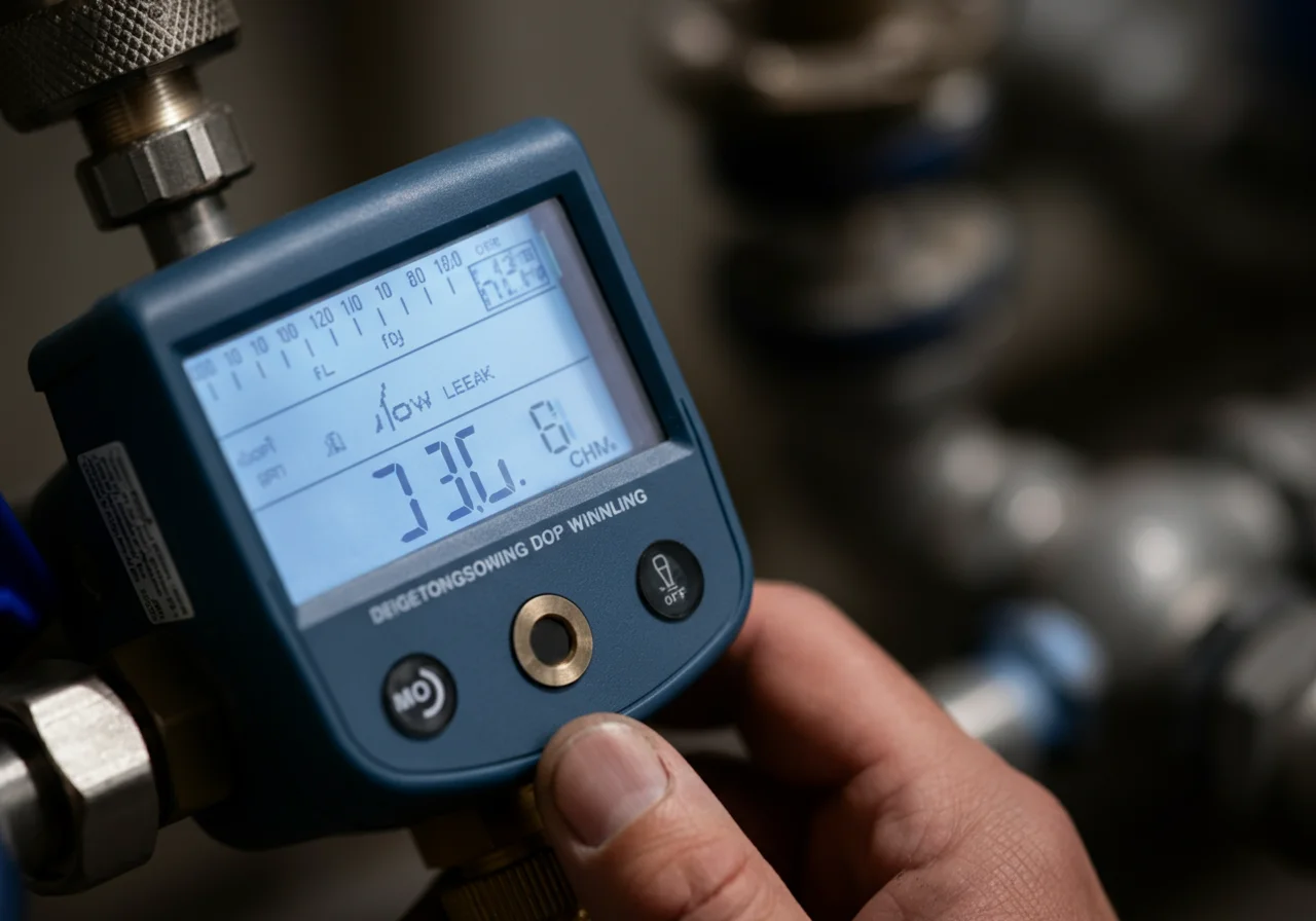
Digital Manometer
The Diagnosis: A Digital Manometer is Your Essential Gas Pressure Gauge
A digital manometer is a precision electronic instrument for measuring fluid pressure, with critical applications in HVAC and plumbing for verifying and adjusting gas pressure. Unlike analog gauges, it provides a direct, high-resolution digital readout, typically in inches of water column (in. WC), the standard unit for natural gas and propane systems. This tool is non-negotiable for performing accurate gas drop tests, setting manifold pressure on furnaces and boilers, and diagnosing pressure-related appliance failures. Incorrect gas pressure is a leading cause of inefficient operation, premature component failure, and safety hazards.
Technical Deep Dive: Operation and Procedure
Using a digital manometer correctly requires understanding its function and following a strict procedural sequence. Here is the step-by-step methodology for the two most common professional applications.
1. Performing a Gas Line Drop Test (Static Pressure Test)
This test verifies the integrity of the gas piping system by ensuring it holds pressure without leaking, as required before appliance activation.
- Tool Setup: Power on your manometer. Select the correct unit (in. WC). Ensure it is zeroed/calibrated per the manufacturer’s instructions.
- System Isolation: At the main gas shutoff, turn the gas off. Disconnect the appliance at its union or at the test port downstream of the main shutoff.
- Connection: Connect the manometer’s pressure port (using appropriate tubing) to the open gas line. The reference port remains open to atmosphere.
- Pressurization: Using a regulated gas source or a hand pump, introduce pressure into the system. For natural gas, a common test pressure is 14 inches of water column (1/2 psi).
- Measurement & Observation: Once pressurized, shut off the source. The manometer will display the static pressure. Observe the reading for a minimum of 10 minutes as specified by code.
- Interpretation: Any drop in the inches water column reading indicates a leak. According to the International Fuel Gas Code (IFGC), a system must hold pressure with no perceptible drop. A failing test mandates a soap-bubble leak check of all fittings.
2. Measuring and Adjusting Appliance Manifold Pressure
This ensures the gas valve is delivering the correct pressure to the burner, which is critical for proper combustion.
- Safety First: Verify the appliance is off and cool. Have a Fluke multimeter ready for electrical checks if needed.
- Access Point: Locate the appliance gas valve’s manifold pressure tap (usually a 1/8″ NPT plug on the outlet side).
- Connection: With the appliance still off, connect the manometer’s pressure port to this tap. Use a Milwaukee adjustable wrench to secure the fitting snugly, avoiding over-torque.
- Live Measurement: Start the appliance and initiate a call for heat. The manometer will now display the live, operating manifold pressure.
- Adjustment: Compare the reading to the manufacturer’s data plate specification (e.g., 3.5 in. WC for natural gas). If adjustment is needed, use a small flat-head screwdriver on the gas valve’s adjustment screw, observing the manometer’s real-time feedback until the correct gas pressure is achieved.
- Final Verification: Cycle the appliance on and off multiple times to ensure the pressure setting is stable.
Code & Compliance: The Legal Framework
Professional work is governed by codes that mandate specific pressures and test procedures. Ignoring these voids liability and creates unsafe conditions.
- International Fuel Gas Code (IFGC) 2021, Section 406: “Piping system pressure tests shall be performed before connections are made to appliances.” It specifies the test duration and acceptable pressure loss (none).
- IFGC, Section 402.11.1 & UPC, Chapter 12: Define the required gas pressure at the appliance inlet, typically between 5-14 in. WC for natural gas, and mandate that appliance manifold pressure conform to the manufacturer’s rating.
- OSHA (29 CFR 1926.153): Governs general safety during handling and testing of fuel gas systems on worksites.
Using a calibrated digital manometer is the only reliable method to demonstrate code compliance. Handwritten pressure readings from your tool serve as legal documentation.
Toolbox: Essential Gear for Precision
Beyond the manometer itself, a professional kit requires supporting tools.
| Tool | Purpose | Pro-Grade Example |
|---|---|---|
| Digital Manometer | Primary measurement of gas pressure in in. WC. | Fieldpiece SDMN5, UEi Test Instruments DAFM4 |
| Adjustable Wrench Set | For connecting to and disconnecting from test ports and valves. | Ridgid Aluminum Adjustable Wrenches |
| Leak Detection Solution | To pinpoint leaks after a failed drop test. | Commercial, non-corrosive bubble solution |
| Assorted Fittings & Tubing | 1/8″ NPT plugs, quick-connect adapters, and reinforced vinyl tubing. | Manufacturer-specific accessory kits |
Safety Warning: Non-Negotiable Protocol
⚠️ GAS WORK IS INHERENTLY HAZARDOUS. Before any procedure:
- Shut off the main gas supply valve.
- Ventilate the work area thoroughly.
- Verify the absence of gas with a combustible gas detector before making connections or disconnections.
- Never use an open flame to check for leaks.
- Only pressurize systems to the levels specified by code for testing—excessive pressure can damage components and create extreme danger.
If you smell gas at any point, stop immediately, evacuate, and call the gas company or emergency services from a safe distance.
External Reference for Technical Foundation
For a fundamental engineering definition of the pressure unit central to this work, the National Institute of Standards and Technology (NIST) provides the authoritative reference.
NIST: Units of Pressure.