Diagnosing a Faulty Electric Heater Element
When an electric water heater fails to produce hot water or its high-limit reset button repeatedly trips, the most common culprits are the upper and lower electric heater element. A systematic diagnosis using a multimeter is the definitive method to confirm an open circuit—a complete break in the element’s internal resistance wire. This guide provides the step-by-step procedure for safe and accurate testing.
Technical Deep Dive: Step-by-Step Element Testing
This procedure assumes you have basic electrical competency and a digital multimeter capable of measuring resistance (Ohms, Ω). Brands like Fluke or Klein Tools offer reliable, auto-ranging models ideal for this task.
Step 1: Initial Isolation and Access
- Shut off the water heater’s circuit breaker.
- Remove the access panels on the side of the tank (typically two, held by screws).
- Peel back the insulation and remove the plastic protective covers to expose the element terminals and thermostats.
- Use your non-contact voltage tester on all exposed wires and terminals to confirm ZERO voltage.
Step 2: Disconnecting Wires for Accurate Testing
- Label or photograph the wire connections for reassembly.
- Using insulated screwdrivers, carefully disconnect all wires from the terminals of the element you are testing. An element must be completely isolated from the circuit for a valid resistance check.
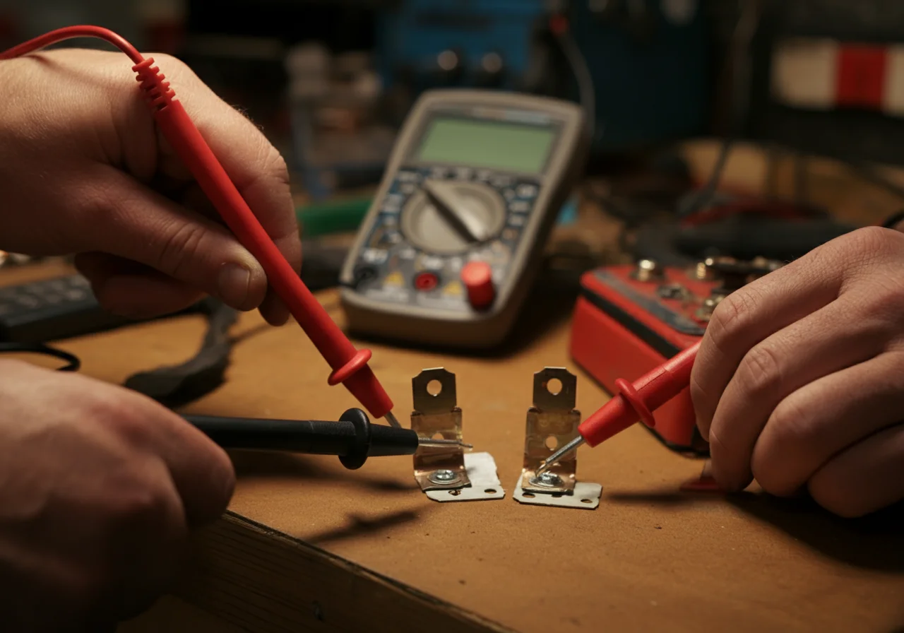
Step 3: The Multimeter Test for Open Circuit
Set your multimeter to the resistance (Ω) function. For a typical 4500-watt, 240-volt element, expect a reading between 10-16 Ω. An infinite resistance reading (OL or “1” on the display) indicates an open circuit and a failed element.
- Testing the Element Itself: Place one multimeter probe on one of the element’s screw terminals. Place the other probe on the second terminal. Note the resistance reading.
- Testing for a Ground Fault: Set the multimeter to continuity or a high resistance scale. Place one probe on an element terminal and the other probe on the bare metal of the tank or the element’s mounting flange. There should be NO continuity (infinite resistance). Any continuity indicates the element has shorted to ground and must be replaced.
Step 4: Interpreting Results and Next Steps
| Multimeter Reading | Diagnosis | Action Required |
|---|---|---|
| 10-16 Ω (for a 4500W/240V element) | Element continuity is good. | Element is functional. Investigate thermostat or wiring. |
| OL (Over Limit) or “1” | Open Circuit. Element has burned out. | Replace the element. |
| 0 Ω or very low resistance | Short Circuit within the element. | Replace the element. |
| Continuity to ground | Ground Fault. Element is leaking current to the tank. | Replace the element immediately. This is a shock hazard. |
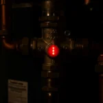
Understanding Reset Button Trips
The high-temperature limit reset button (usually red) is a safety device that trips when the water temperature exceeds approximately 150°F. A single trip may be reset, but repeated tripping signals a systemic failure. The root cause is often a failed lower element combined with a faulty upper thermostat, causing the upper element to overheat the tank. Simply resetting the button without performing the multimeter test on both elements and thermostats is a temporary and potentially dangerous fix.
Code & Compliance Considerations
All repairs must adhere to the National Electrical Code (NEC) and local plumbing codes. Key articles include:
- NEC Article 422 – Appliances: Governs the installation and branch-circuit requirements for fixed electric water heating appliances.
- NEC 110.3(B): Requires equipment to be installed and used in accordance with listed instructions. Always follow the manufacturer’s torque specifications for element installation.
- IPC/UPC on Draining & Pressure: When replacing an element, you must fully drain the tank. This ties into code requirements for proper drain valves and pressure relief valve operation (ASSE 1017/ANSI Z21.22). A faulty relief valve can contribute to overheating.
OSHA standards (29 CFR 1910.147) mandate the lockout/tagout procedure emphasized in the safety warning for any service and maintenance activities.
Essential Toolbox for the Job
- Digital Multimeter: A quality auto-ranging model from Fluke or Klein Tools.
- Non-Contact Voltage Tester: For initial and verification safety checks.
- Insulated Screwdriver Set: For terminal connections.
- Element Wrench: A dedicated socket wrench, often 1-1/2″, for removing and installing elements. A Ridgid model is a durable choice.
- Garden Hose & Bucket: For draining the tank.
External Reference for Further Detail
For a deeper understanding of electrical resistance theory and how it applies to heating elements, the fundamental principles of Joule Heating (Resistive Heating) are explained in detail. This resource covers the science behind why a broken (open) element fails to generate heat.
Final Professional Note: Always replace a water heater element with one of identical voltage, wattage, and physical size. Installing a higher-wattage element than the wiring and thermostat are rated for is a code violation and a severe fire hazard. If diagnostic steps exceed your comfort level, consult a licensed electrician or plumber.