Electric Heater Breaker Size
Selecting the correct water heater breaker size is a non-negotiable step in any installation or replacement. An undersized breaker will nuisance trip; an oversized one creates a severe fire hazard by allowing wires to overheat. This guide provides the calculations and code-backed procedures for sizing breakers and conductors for common 4500W and 5500W residential electric water heaters.
The Diagnosis: Sizing the Circuit for the Load
An electric storage water heater is a continuous duty, non-motor load. The circuit breaker’s primary role is to protect the branch circuit wiring from overheating, not the appliance itself. Therefore, sizing follows a strict sequence: calculate the heater’s maximum amperage draw, apply National Electrical Code (NEC) rules for continuous loads, then select a wire wire gauge with an ampacity that meets or exceeds the breaker rating.
Technical Deep Dive: Calculation & Installation Procedure
Follow this step-by-step process to determine the correct components. You will need the water heater’s nameplate, which lists the voltage and wattage of each heating element.
Step 1: Calculate the Maximum Amperage Draw
Use the power formula: Amps = Watts / Volts. Most residential electric water heaters operate at 240 volts.
- For a 4500-watt, 240-volt element: 4500W / 240V = 18.75 amps.
- For a 5500-watt, 240-volt element: 5500W / 240V = 22.92 amps.
Critical Note: Only one heating element is energized at a time (upper thermostat calls for heat first). You size the circuit for the higher-wattage element if they differ, but typically both are the same rating.
Step 2: Apply NEC Rules for Continuous Load
The NEC defines a continuous load as one where the maximum current is expected to continue for 3 hours or more (NEC Article 100). A water heater qualifies. For continuous loads, the circuit must be sized at 125% of the load.
- 4500W Calculation: 18.75A x 1.25 = 23.44 amps.
- 5500W Calculation: 22.92A x 1.25 = 28.65 amps.
Step 3: Select the Standard Breaker Size
Circuit breakers are manufactured in standard sizes. You must select the next standard size up that can handle the calculated continuous load. Common residential single-pole breaker sizes are 15A, 20A, 30A, 40A, and 50A.
| Element Wattage | Calculated Load (125%) | Minimum Breaker Size | Typical Industry Standard |
|---|---|---|---|
| 4500W @ 240V | 23.44A | 30-Amp (Next standard size above 23.44A) | 30-Amp Double-Pole |
| 5500W @ 240V | 28.65A | 30-Amp (28.65A ≤ 30A) | 30-Amp Double-Pole |
Warning: Do not use a 40-amp breaker for a 5500W heater on a cable rated for 30 amps. The breaker protects the wire, not the appliance.
Step 4: Determine the Correct Wire Gauge (Conductor Size)
The wire must have an ampacity (current-carrying capacity) at least equal to the 125% continuous load calculation before you apply the breaker size. Refer to NEC Table 310.16 for copper wire ampacities (common for branch circuits). Assume NM-B (Romex) cable in a typical residential installation at 60°C or 75°C column.
| Wire Gauge (Copper) | 60°C Ampacity | 75°C Ampacity | Sufficient for Load? |
|---|---|---|---|
| 10 AWG | 30A | 35A | Yes, for 4500W (23.44A load). A 30A breaker protects 10 AWG wire. |
| 10 AWG | 30A | 35A | Yes, for 5500W (28.65A load). Load (28.65A) is less than wire’s 30A 60°C rating. A 30A breaker is correct. |
| 12 AWG | 20A | 25A | No. Insufficient for either calculated load (23.44A, 28.65A). |
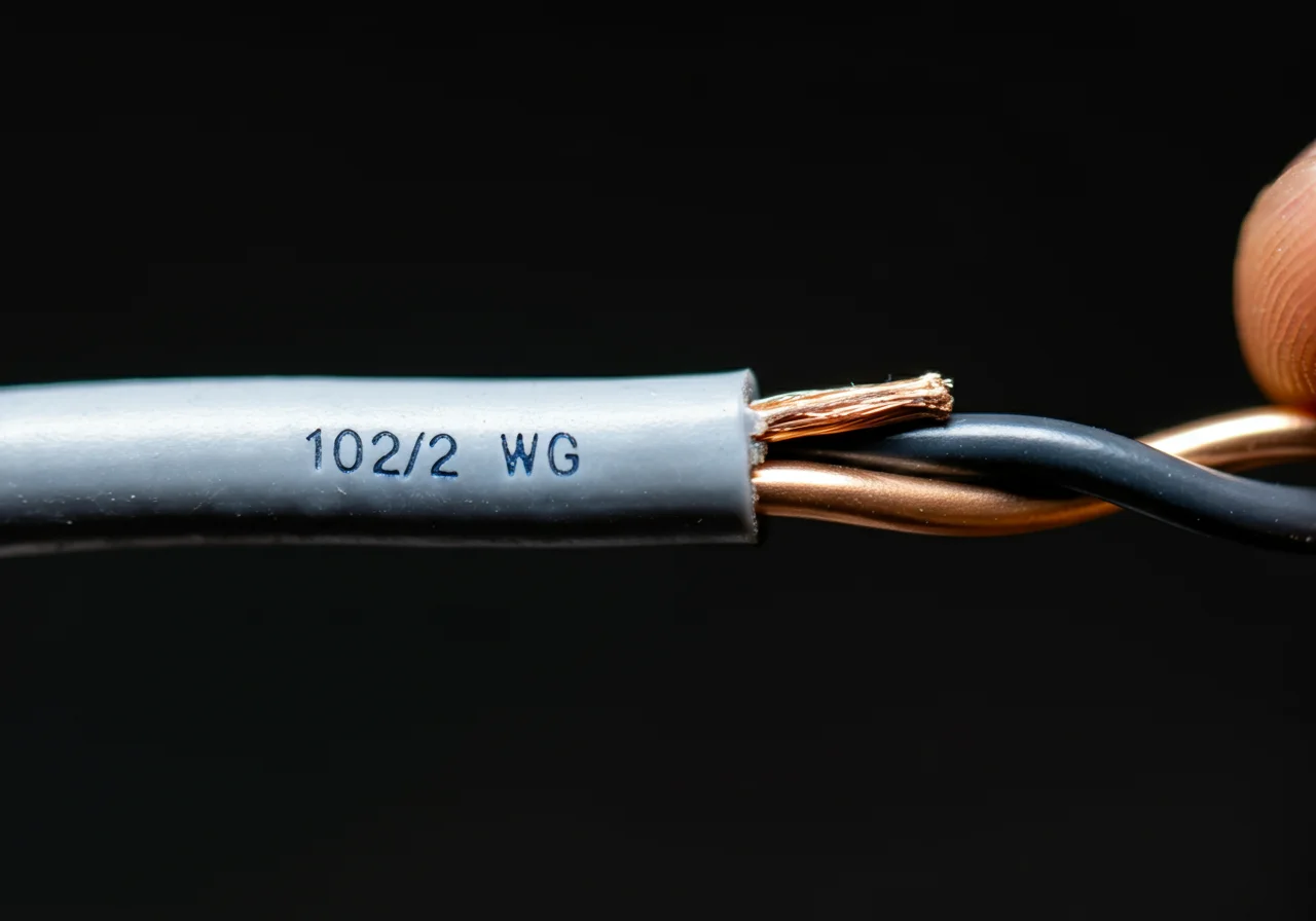
Standard Practice: A 10/2 with ground NM-B cable protected by a 30-amp double-pole breaker is the standard, code-compliant installation for both 4500W and 5500W 240V residential electric water heaters.
Code & Compliance
All work must comply with the National Electrical Code (NFPA 70) and local amendments.
- NEC 422.13 (Storage-Type Water Heaters): Requires a branch circuit rated at 125% of the heater’s nameplate rating.
- NEC 210.20(A) & 240.4(B): Govern overcurrent protection device sizing. The next standard size up rule is permitted for the scenarios outlined here.
- NEC 110.14(C): Requires termination temperature ratings to be observed. For most residential breakers and devices, the 60°C column is the starting point for #14 through #1 AWG conductors.
- NEC 250.110: Mandates equipment grounding. The bare or green equipment grounding conductor in the NM-B cable must be connected to the green ground screw on the water heater junction box and the panel’s ground bus.
Toolbox
Use professional-grade tools for reliable, safe work.
- Diagnostic/Metering: A true-RMS digital multimeter like a Fluke T5-600 or T6-600 to verify voltage and continuity.
- Installation: A torque screwdriver to achieve proper termination torque on lugs (prevents loose connections, a major cause of failure). For cable prep, a Ridgid or Milwaukee wire stripper/cutter.
Safety Warning
ELECTRICAL WORK CAN BE FATAL AND CAUSE PROPERTY DAMAGE. Before starting any work, turn off the main breaker in the service panel and use a voltage tester to confirm power is off at the water heater junction box and the panel terminals. Only qualified individuals familiar with the NEC and safe work practices should perform this installation. Permits and inspections are often required.
External Reference
For the definitive source on conductor ampacities and installation rules, consult the latest edition of the NFPA 70: National Electrical Code. A key technical resource for understanding electrical calculations is the Wikipedia entry on Electric Power, which details the fundamental formulas.