Tankless Flow Sensor Clean
The Diagnosis: A Faulty Flow Sensor is a Primary Cause of Ignition Failure
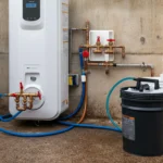
A tankless water heater flow sensor is a critical component that tells the unit’s control board when and how much water is moving through the heat exchanger. When this sensor fails due to mineral scale or debris, the unit will not receive the signal required to initiate the gas valve and ignition sequence, resulting in no hot water. This guide provides a step-by-step procedure for diagnosing, removing, and cleaning a turbine-style flow sensor to resolve common ignition failures and error codes related to flow detection.
Technical Deep Dive: Step-by-Step Sensor Service
This procedure applies to most residential tankless units with a removable turbine sensor. Always consult your specific model’s service manual for variations.
- Power Down & Isolate the Unit: Turn off the electrical breaker(s) supplying the tankless heater. Shut off the gas supply valve. Close both the hot and cold water isolation valves on the unit.
- Relieve System Pressure: Open a hot water faucet in the home. Locate the unit’s pressure relief valve or service valves and open them to drain water from the heat exchanger and piping.
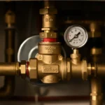
- Access the Sensor Housing: Remove the unit’s front cover. The flow sensor is typically located on the cold water inlet manifold or within the water module assembly. Identify the sensor—it will have electrical connectors and be seated in a brass or plastic housing in the water path.
- Remove the Sensor: Disconnect the electrical plug. Using the appropriate size wrench (often 1-1/16″ or 27mm), unscrew the sensor housing from the waterway. Have a small bucket and towel ready for residual water.
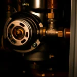
- Disassemble and Inspect: Carefully remove the turbine wheel and magnet assembly from the housing. Inspect for scale buildup (white/green crust) or silt/debris. The turbine should spin freely with no resistance.
- Cleaning Process:
- Submerge the turbine and housing in pure, undiluted white vinegar or a manufacturer-approved descaling solution for 15-20 minutes.
- Use a soft-bristle brush (an old toothbrush works) to gently remove all deposits. Do not use abrasives or metal brushes.
- Rinse all components thoroughly with clean water.
- Inspect the internal chamber of the unit’s waterway where the sensor seats for debris and flush if necessary.
- Reassembly and Testing: Ensure all O-rings or gaskets are in good condition; replace if worn. Reinsert the turbine, ensuring it spins freely. Hand-tighten the sensor housing, then secure with a wrench using moderate torque—over-tightening can crack the housing. Reconnect the electrical plug. Restore water, power, and gas. Purge air from the lines by running hot water at a faucet for several minutes. Test for proper ignition and operation.
Code & Compliance: System Integrity is Paramount
While cleaning a sensor is a maintenance task, the re-assembly must adhere to plumbing code standards to prevent leaks and ensure safety.
- IPC P2904.6 (Accessibility): All components must be reassembled to maintain clear access for future inspection, service, repair, and replacement.
- UPC 609.3 (Joints and Connections): All re-made connections must be “tight and made in accordance with the manufacturer’s instructions.” This underscores the importance of correct gasket placement and proper torque on the sensor housing.
- General Safety: A leaking fitting can cause water damage or, in the case of a gas unit, create a hazardous environment if water contacts electrical components.
Understanding Related Issues: Cold Water Sandwich and Error Codes
Cold Water Sandwich
This phenomenon, where a burst of cold water is felt during otherwise hot water use, is often mistakenly attributed to a flow sensor issue. The cold water sandwich effect is typically a function of the unit’s minimum flow rate and heat exchanger response time, not a faulty sensor. A properly functioning but slightly scaled sensor may cause delayed ignition, exacerbating the sensation. Ensuring the sensor is clean helps the unit respond at the correct, designed flow rate, minimizing this issue.
Error Code Diagnosis
Most tankless units will display a specific error code when the flow sensor circuit fails. Common codes include:

| Manufacturer | Example Error Code | Likely Meaning |
|---|---|---|
| Rinnai | 11 | Ignition failure (often due to no gas or no proven flow) |
| Navien | 003 | Flow sensor signal error |
| Noritz | 11 | Water flow problem detected |
Note: Always cross-reference the code in your official manufacturer’s manual. A persistent code after a thorough cleaning may indicate a failed sensor requiring replacement.
Toolbox: Recommended Tools for the Job
- Adjustable Wrench or Correct Size Socket: For the sensor housing nut (e.g., Ridgid aluminum adjustable wrench).
- Multimeter: For advanced diagnostics to check sensor continuity or hall-effect switching (e.g., Fluke T5-600).
- Soft-Bristle Brushes & Container: For cleaning components.
- Replacement O-Rings/Gaskets: Manufacturer-specific kit for the water module.
Safety Warning
FAILURE TO FOLLOW THESE INSTRUCTIONS CAN RESULT IN PROPERTY DAMAGE, ELECTRICAL SHOCK, OR EXPLOSION HAZARD. You must shut off the electrical power at the breaker, shut off the gas supply valve, and shut off the water supply valves to the unit before beginning any work. If you are not confident in your ability to perform this task safely, contact a licensed plumbing or HVAC professional.
External Reference
For a general technical overview of flow measurement principles used in these sensors, you can review the Wikipedia entry on Flow Measurement. For all safety procedures regarding gas appliances, refer to resources from the U.S. Consumer Product Safety Commission (CPSC).